


Blog
Automotive Robotic Welding Systems: Spot, MIG & Laser Welding for Body-in-White

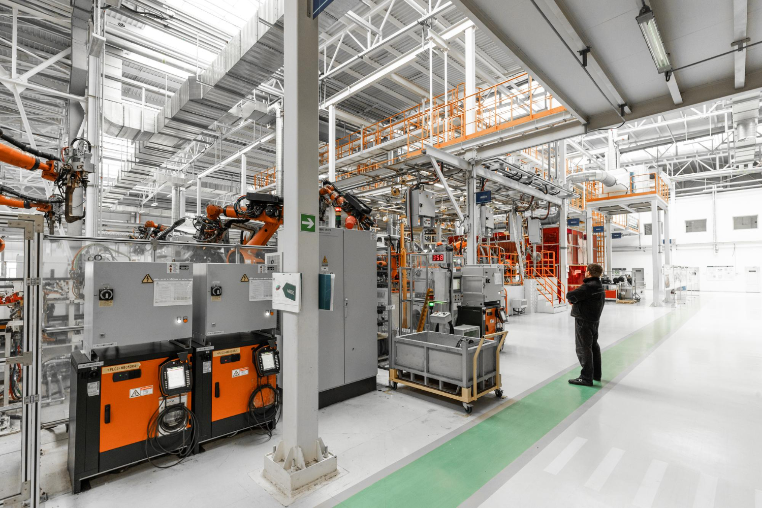
Automotive robotic welding systems use programmable robotic arms to join vehicle body panels through spot welding, MIG welding, or laser welding, delivering the speed and placement consistency that body-in-white assembly requires at production volume. A single vehicle body can involve anywhere from a few hundred to several thousand individual welds, and robotic systems perform them in the same position, at the same strength, on every single unit, in a way manual welding simply can’t replicate hour after hour across a full shift.
That consistency is really the whole story behind why robotic welding became the backbone of body-in-white assembly decades ago and remains that way today. Here’s how the three main welding processes differ, what makes a robotic welding cell actually work, and what to look for if you’re evaluating or upgrading one.
Why Body-in-White Welding Was Automation’s First Automotive Application
Body-in-white — the welded structural shell of a vehicle before paint, trim, or glass go on — was one of the earliest and most natural fits for industrial robotics in automotive manufacturing, and it’s still one of the heaviest automated stages on most lines. A few reasons explain why.
The sheer weld count makes manual welding at scale nearly impossible to do consistently; a body shell with 3,000-5,000 spot welds simply can’t be hand-welded by a person with the same placement accuracy, weld after weld, shift after shift. The physical demands of welding — awkward positions, repetitive motion, heat and fume exposure — make it one of the more punishing manual tasks on a traditional line, which gives automation a strong safety case on top of a quality case. And the structural importance of these welds means a weak or misplaced weld isn’t just a cosmetic issue, it’s a safety issue, which pushes manufacturers toward the kind of repeatable precision robots deliver far more reliably than human hands over a long shift.
The Three Core Welding Processes in Automotive Robotics
Spot Welding
Resistance spot welding remains the dominant joining method for automotive body panels. Two electrodes clamp the panels together and pass an electrical current through the joint, generating localized heat that fuses the metal at that point. Robotic spot welding guns move from point to point across the body, completing hundreds of welds per vehicle in a tightly choreographed sequence.
Spot welding’s advantages are speed and simplicity — each weld takes a fraction of a second, and the process is well understood, well standardized, and supported by decades of automotive engineering data. Its main limitation is that it only works well on overlapping sheet metal joints within a certain thickness range, which is why it’s not the only process used on a modern body shell.
MIG Welding
Metal Inert Gas (MIG) welding feeds a continuous wire electrode through a welding gun while shielding gas protects the weld pool from contamination. Unlike spot welding’s point-by-point approach, MIG welding creates a continuous seam, making it better suited for joints that need a stronger, longer bond — structural frame components, certain chassis joints, and areas where spot welding’s point-contact approach isn’t sufficient.
Robotic MIG welding requires more sophisticated path programming than spot welding, since the robot has to maintain a steady travel speed, consistent torch angle, and correct standoff distance along the entire seam to produce a quality weld. This makes MIG welding cells somewhat more demanding to program and commission than spot welding cells, but the payoff is a stronger, more versatile joint where the application calls for it.
Laser Welding
Laser welding has become increasingly common on modern automotive lines, particularly for roof seams, certain structural joints, and applications where a narrower, more precise weld with minimal heat distortion matters. A focused laser beam melts the metal at the joint with extremely tight precision, producing a clean, strong weld with a much smaller heat-affected zone than spot or MIG welding.
The tradeoff is cost and precision requirements — laser welding systems are more expensive than spot welding equipment, and they demand tighter part fit-up tolerances going into the weld, since the process has less tolerance for gaps or misalignment than spot welding does. For manufacturers producing EVs with lightweight materials or unconventional joint geometries, laser welding is increasingly the process of choice where its precision advantages outweigh the added cost.
How a Robotic Welding Cell Actually Works Together
A welding robot by itself doesn’t make a functioning cell. A real automotive robotic welding system typically includes several coordinated pieces:
The robot and welding equipment — the arm itself, paired with the spot gun, MIG torch, or laser head appropriate to the process, mounted and calibrated for the specific joint geometry it needs to reach.
Fixturing that holds the body panels in precise position throughout the weld sequence, since even a small amount of part movement during welding can throw off placement accuracy or weld quality.
Vision or sensor systems that verify part position before welding begins, catching a misaligned or missing panel before the robot wastes a cycle welding something that isn’t correctly positioned.
Weld monitoring and data logging systems that track key parameters — current, voltage, weld time, electrode force — for every single weld and tie that data back to the specific vehicle’s serial number. This has become a near-standard requirement in modern body-in-white welding automation, since OEMs increasingly expect documented proof that every structural weld met spec, not just a sampling-based quality check.
Safety guarding and interlocks that keep operators safely outside the robot’s working envelope during the weld cycle, given the heat, electrical current, and fast motion involved.
Why Weld Monitoring and Data Logging Matter More Than Ever
A generation ago, weld quality on many lines was verified through periodic destructive testing — pulling a sample body apart to check weld strength and extrapolating that the rest of the welds on similar vehicles met spec too. That approach works statistically, but it doesn’t catch an individual defective weld on an individual vehicle.
Modern weld monitoring systems record parameters for every weld, in real time, and flag any reading that falls outside an acceptable range immediately, often before the vehicle even leaves that station. This data gets tied to the vehicle’s serial number and stored, creating a full traceability record that can be pulled up months or years later if a quality question ever arises.
This isn’t just a nice-to-have anymore. OEM quality requirements increasingly expect this level of documentation as standard practice, and suppliers who can’t provide it are at a real disadvantage during sourcing decisions. Beyond the compliance angle, this data is genuinely useful operationally — it lets engineers spot a slowly degrading electrode or a drifting process parameter well before it produces an actual defect, turning weld data into a maintenance and quality tool rather than just a record-keeping requirement.
Choosing the Right Welding Process for Your Application
Manufacturers evaluating a new or upgraded welding cell usually land on one of three decisions, and the right call depends on the specific joint.
1)Choose spot welding for standard overlapping sheet metal joints at typical automotive gauge thicknesses, where speed and cost efficiency matter most and the joint doesn’t require continuous seam strength.
2)Choose MIG welding for structural joints that need a continuous bond, thicker material combinations spot welding can’t handle well, or applications where a stronger joint justifies the added programming and cycle time.
3)Choose laser welding for precision applications with tight heat-affected zone requirements, lightweight material joints common in EV construction, or visible seams like roofline joints where weld appearance and minimal distortion matter.
Many modern body shops actually use all three processes on a single vehicle, applying each one to the joints it handles best rather than standardizing on a single method across the whole body structure.
What to Look for When Evaluating a Welding Cell Upgrade or New Install
A few practical considerations tend to separate a well-specified welding project from one that underperforms once it’s running.
Match the process to the actual joint requirements, not just what the plant has used historically. A process that worked well on a previous model may not be the right fit if material gauges or joint geometry change on a new platform.
Confirm fixturing tolerance matches the welding process chosen. Laser welding in particular demands tighter part fit-up than spot welding tolerates comfortably, and underspecified fixturing is a common source of early quality issues on laser cells.
Build weld monitoring and data logging in from the start, rather than treating it as an add-on. Retrofitting monitoring capability onto an existing cell is possible but usually costs more and integrates less cleanly than designing it in from day one.
Plan for electrode and consumable maintenance, since spot welding electrodes wear with use and gradually affect weld quality if not maintained on a proper schedule. A well-designed cell makes this routine maintenance easy to access, not an afterthought squeezed into a tight footprint.
Work with an integrator who has real experience in the specific process you’re choosing. Spot welding, MIG welding, and laser welding each demand different programming expertise and process knowledge, and a team strong in one isn’t automatically strong in all three.
How Robotic Welding Fits Into the Broader Assembly Process
Welding cells don’t operate in isolation. They sit inside the larger flow of automotive assembly automation, receiving stamped panels from upstream stations and passing a completed body shell downstream to paint and final assembly. A welding cell that runs beautifully on its own but doesn’t sync well with the stations feeding it or receiving from it still creates problems for the line as a whole.
This connection matters in a few practical ways. Panel delivery timing has to match the welding cell’s actual cycle, since a station that’s ready to weld but waiting on a delayed part isn’t producing anything. Buffer capacity before and after the welding cell needs to account for the cell’s real-world reliability, not just its rated cycle time, so a brief hiccup doesn’t cascade into a full line stop. And the data generated by weld monitoring systems is most valuable when it connects into the plant’s broader quality and production tracking, rather than living in an isolated system only the welding team ever looks at.
Manufacturers planning a new welding cell get the best results when they think about these connections from the start, rather than treating the welding station as a standalone purchase disconnected from the rest of the line’s design.
Common Issues That Show Up in Robotic Welding Cells
A handful of recurring issues tend to surface in robotic welding operations, and knowing them ahead of time helps with both planning and troubleshooting.
Electrode wear degrading spot weld quality gradually. Electrodes mushroom and wear with repeated use, and if dressing or replacement schedules aren’t followed closely, weld quality can drift slowly enough that it’s not obvious until monitoring data flags a pattern.
Part fit-up variation throwing off laser welding results. Because laser welding tolerates less gap or misalignment than spot or MIG welding, any upstream variation in panel stamping or fixture wear shows up as weld defects faster on laser cells than on more forgiving processes.
Weld spatter and fume buildup affecting sensor accuracy. Vision systems and certain sensors positioned near welding operations can accumulate residue over time, gradually reducing their accuracy if cleaning and maintenance schedules aren’t followed.
Robot path drift from fixture or tooling wear. A robot’s programmed path assumes the part and fixture are exactly where they were during initial programming. As fixtures wear slightly over months of production, small discrepancies can accumulate into weld placement issues that aren’t always obvious until a quality review catches the pattern.
Most of these issues are manageable with a solid preventive maintenance schedule and attentive weld monitoring, but they’re worth planning for during the original cell design rather than discovering them after the fact.
Building Welding Cells That Hold Up Over the Long Run
Automotive robotic welding systems are one of the clearest cases where getting the underlying engineering right pays off for years. A well-specified cell, matched to the right process for each joint and backed by solid weld monitoring, produces consistent, documented quality with minimal ongoing drama. A poorly matched or undermonitored cell tends to generate recurring quality questions that are expensive and time-consuming to chase down after the fact.
Fenbotics designs and integrates robotic welding systems across spot, MIG, and laser processes for automotive body-in-white applications. Based in Lancaster, South Carolina, our team matches the welding process to your actual joint requirements, builds weld monitoring and data logging into the system from the start, and designs fixturing that holds the tolerances each process actually demands. If you’re planning a new welding cell or evaluating whether your current setup still fits your product, we’re glad to look at your specific body structure and talk through which process makes the most sense.