


Blog
Automotive Assembly Automation: Line Design, Process & Best Practices

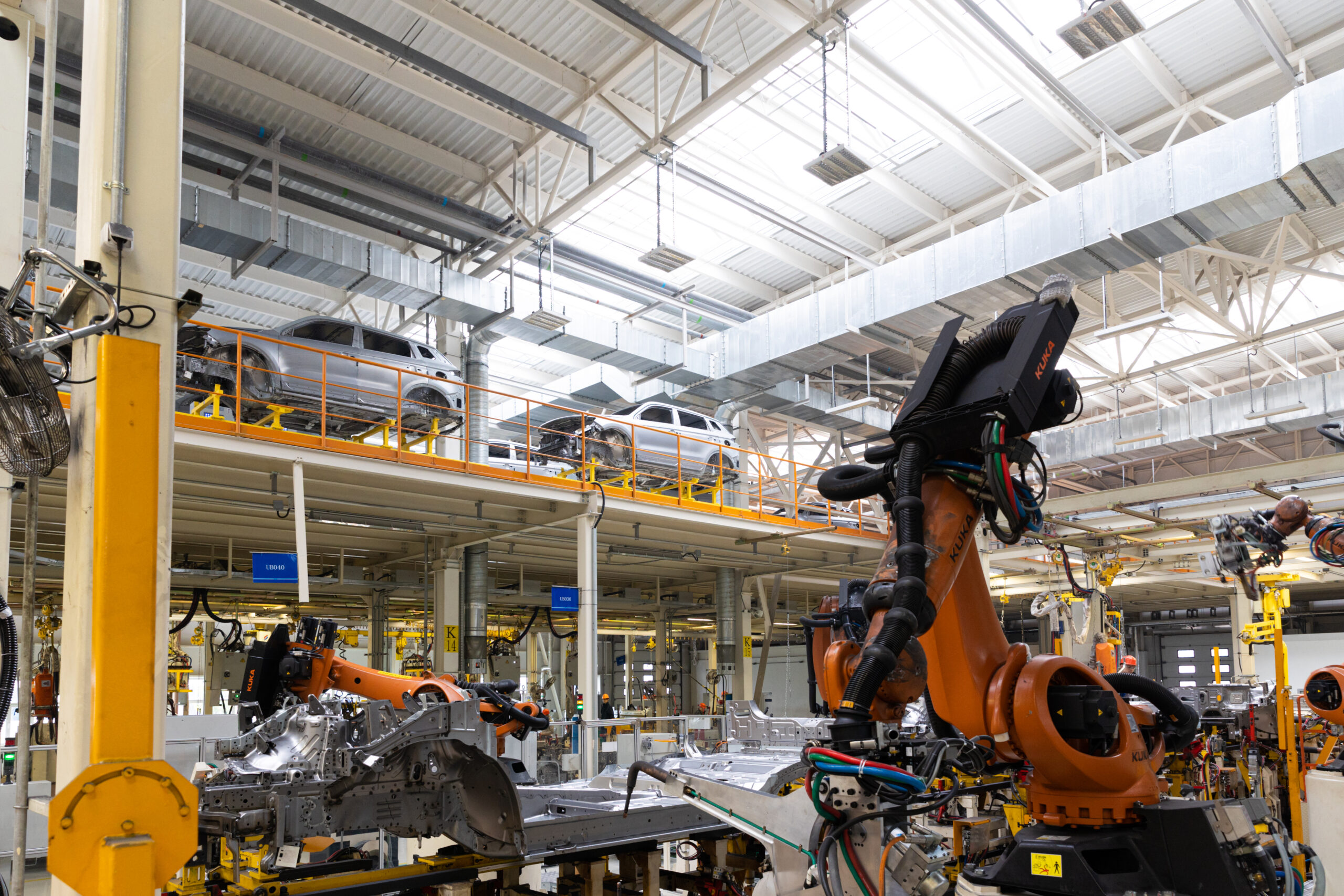
Automotive assembly automation is the use of robotics, conveyors, and controlled workstations to build vehicles along a structured production line, with each station handling a specific task joining, fastening, installing, testing — in a fixed sequence designed around a target cycle time. Getting it right isn’t really about which robot brand you pick or how fast a single station can run. It’s about how well the entire line is designed to work together, station by station, so parts flow smoothly from raw material to finished vehicle without one slow or unreliable link dragging down everyone downstream.
That distinction automation as individual equipment versus automation as line design is where a lot of assembly projects either succeed or quietly underperform for years. Here’s how good automotive assembly line design actually works, what separates a well-planned line from a poorly planned one, and the best practices worth building into your next layout.
Line Design Starts With the Constraint That Matters Most: Time
Before any equipment gets selected, a well-designed line starts with time the maximum time allowed per unit to hit your required daily output. If your plant needs to produce 480 vehicles in a 16-hour shift, that works out to a time of 2 minutes per vehicle, and every single station on the line has to complete its task within that window, or the whole line slows to match its weakest point.
This sounds obvious, but it’s the single most common mistake in assembly automation planning: equipment gets selected station by station, based on what looks capable in isolation, without checking that every station’s actual cycle time including part loading, processing, and unloading fits inside the shared time. A station that’s individually impressive but consistently 10 seconds over time doesn’t just underperform; it becomes the ceiling for the entire line’s output.
The Core Principles of Good Assembly Line Design
Balance the Line, Not Just the Stations
Line balancing means distributing tasks across stations so that no single station becomes a bottleneck while others sit underutilized waiting for work. This often means splitting a complex task across two stations, or combining two quick tasks into one station, purely to keep cycle times even across the whole line. It’s less intuitive than it sounds the “correct” split usually isn’t obvious until you’ve mapped out every task’s actual time in detail.
Sequence Automated and Manual Stations Deliberately
Very few automotive lines are 100% automated, and that’s by design, not a limitation. Tasks requiring dexterity, judgment, or handling highly variable components like certain wiring harness installations or trim fitting often still favor manual labor, at least for now. Good line design places these manual stations deliberately, with buffer capacity where needed, rather than letting automated and manual stations collide unpredictably.
Design for Flow, Not Just for Individual Stations
A line is a system, and the connections between stations matter as much as the stations themselves. Conveyor speed, buffer zones, and part orientation between stations all affect whether parts arrive at the next station ready to process, or whether they need extra handling that eats into your time budget. This is where automotive production line automation and assembly line design overlap heavily; the material flow between stations is just as much a design decision as the stations themselves.
Build in Line-Level Redundancy Where It’s Cheap
A single point of failure on a critical station can stop an entire line. Where the cost is reasonable, designing in redundancy a backup weld gun, a secondary sensor path, a buffer that lets downstream stations keep running briefly during an upstream hiccup prevents a minor equipment issue from becoming a full line stoppage.
Designing for Multi-Model Production
Modern automotive plants rarely build just one product on a line anymore. Multiple trims, body styles, or even different powertrains gas, hybrid, electric often run down the same physical line, and this reality shapes assembly line design more than almost anything else today.
Multi-model robotic assembly requires stations that can recognize which variant is coming through and adjust their process accordingly with different weld patterns, different fastening torques, different part orientations without a manual changeover or a line stop. This typically means:
- Vision-based part identification at the start of the line or at key stations, so the system automatically knows which variant it’s handling
- Program libraries within the PLC and robot controllers, with pre-loaded parameter sets for each model variant that load instantly based on that identification
- Fixturing designed for multiple part geometries, either through adjustable tooling or quick-swap fixture plates rather than single-purpose tooling
Lines designed this way from the start handle model mix far more gracefully than lines originally built for a single product and retrofitted later for variety which almost always involves compromises in cycle time or reliability.
Rapid-Changeover Fixturing: The Unsung Hero of Flexible Lines
If multi-model production is the requirement, rapid-changeover fixturing is often the actual mechanism that makes it possible. Traditional fixed tooling holds one part geometry precisely but can’t adapt to another without physical reconfiguration swapping fixture plates, adjusting clamps, sometimes taking a station offline for hours.
Rapid-changeover fixturing is designed to switch between part variants in minutes rather than hours, using tooling elements like:
- Modular fixture bases with quick-release locating pins that accept different top plates for different part variants
- Automated clamp repositioning, where actuators move clamps into the correct position for the current variant based on the same part-identification signal driving the rest of the station
- Standardized interface points between fixtures and the station’s base structure, so a new part variant’s tooling can be designed and swapped in without redesigning the whole station
The upfront engineering cost of rapid-changeover fixturing is real, but for lines running genuine model variety, it usually pays for itself quickly compared to the alternative either accepting slower changeovers that eat into production time, or building entirely separate lines for each variant.
Common Line Design Mistakes That Show Up Later
A few recurring mistakes tend to surface only after a line is already running, which makes them expensive to fix.
Designing to average cycle time instead of worst-case cycle time. A station that hits its target time on a “clean” part run but struggles with the occasional out-of-spec part or awkward orientation will create intermittent bottlenecks that are maddening to diagnose because they don’t show up every cycle.
Underestimating buffer requirements between stations. Zero buffer between stations means any hiccup at one station immediately stalls the one before it. Oversized buffers waste floor space and add complexity. Getting this balance right requires understanding the actual reliability of each station, not just its rated cycle time.
Treating safety guarding as an afterthought in layout. Retrofitting safety zones after a layout is finalized often means awkward compromises guarding that blocks maintenance access, or safety zones that force operators into inefficient paths. Building safety requirements into the layout from the beginning avoids this entirely.
Not planning for maintenance access. A beautifully compact layout that leaves no room for a technician to actually reach a robot’s control cabinet or a station’s wear components turns routine maintenance into a multi-hour ordeal every time it’s needed.
Ignoring future flexibility during initial design. Plants that design purely around today’s single-model volume often find themselves paying far more to retrofit flexibility in a year or two than they would have spent building it in from the star a pattern that shows up constantly in multi-model production upgrades.
Best Practices for Planning an Assembly Automation Project
Pulling the principles above into a practical planning approach, a few habits consistently separate well-executed line design projects from troubled ones:
- Map every station’s real cycle time before selecting equipment — including load, process, and unload time, not just the marketed cycle speed of the core machine.
- Build the line balance model before finalizing layout, so task distribution across stations is deliberate rather than discovered by trial and error after installation.
- Design fixturing and controls around your actual product roadmap, not just your current single-model volume, especially if model variety is likely within the equipment’s working life.
- Involve maintenance and safety input early, not as a final review step, since both affect layout decisions that are expensive to change later.
- Plan buffer zones based on real reliability data from similar past stations, not optimistic assumptions about uptime.
- Pilot new station designs on a smaller scale where possible, catching balancing and reliability issues before committing to a full multi-station rollout.
How Vision and Sensors Support Line-Level Coordination
It’s worth calling out that a lot of what makes multi-model, flexible line design actually work in practice comes down to vision and sensor systems doing coordination work between stations, not just quality checks within them. A vision system at the start of the line that identifies which variant just entered doesn’t just trigger that one station’s program; it can pass that identification downstream through the PLC network, so every subsequent station already knows what’s coming before the part physically arrives. This kind of forward signaling reduces the chance of a station being caught off guard by an unexpected variant and having to pause or reject a part mid-cycle.
The same principle applies to buffer and conveyor logic. Sensors tracking part position and station status throughout the line let the control system make small real-time adjustments slowing a conveyor slightly, holding a part in a buffer an extra few seconds that keep the whole line running smoothly instead of hard-stopping the moment one station falls slightly behind. This kind of dynamic coordination is a meaningful step up from older, more rigid line designs where a hiccup at one station simply cascaded into a full stop everywhere else.
Measuring Whether Your Line Design Is Actually Working
Once a line is running, a handful of metrics tell you whether the design is performing the way it was planned to:
- Overall Equipment Effectiveness (OEE) at the line level, not just individual stations, shows whether the system as a whole is hitting its throughput potential.
- Bottleneck frequency — tracking which station most often causes the line to fall behind time — tells you where the original line balance may have been off, or where a station’s real-world reliability didn’t match its rated specs.
- Changeover time for multi-model lines is a direct measure of whether rapid-changeover fixturing and programming are delivering the flexibility they were designed for.
- Buffer utilization shows whether buffer zones are sized correctly, consistently empty buffers suggest they were oversized, while buffers that constantly hit capacity suggest they’re undersized relative to actual station reliability.
Reviewing these numbers regularly, rather than only at commissioning, is what turns a good initial design into a line that keeps improving over its working life.
Line Design Is Where Automation Strategy Actually Gets Decided
Individual robots and vision systems get most of the attention in automation conversations, but the real performance of an automotive assembly line comes down to how well those components are sequenced, balanced, and connected as a system. A brilliant individual station on a poorly designed line still underperforms and a well-balanced line built around thoughtful time planning, flexible fixturing, and realistic buffer design consistently outperforms one built station-by-station without that bigger-picture thinking.
Fenbotics approaches every assembly automation project from that line-level perspective. Based in Lancaster, South Carolina, our team starts with your actual take time, model mix, and floor layout before specifying a single piece of equipment, so the stations we design work together as one balanced system rather than a collection of individually capable machines. If you’re planning a new assembly line or reworking an existing one to handle more model variety, we’re glad to look at your specific process and talk through what good line design should look like for your plant.